
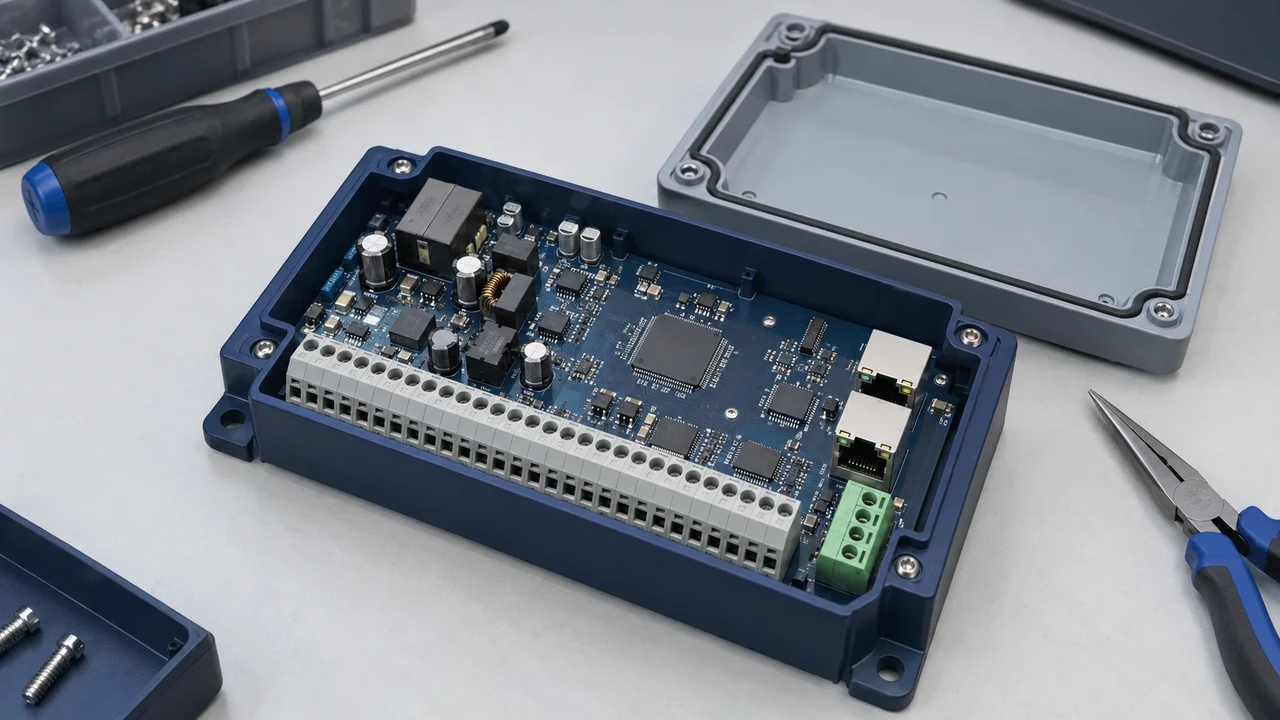
Start an industrial-control component requirement by defining the module boundary, then separate control, signals, power, interconnects and protection. A list containing only “processor, power IC and connector” is not yet enough for selection or procurement. This guide focuses on low-voltage control and input/output modules, not high-voltage motor power stages, complete safety-PLC design or a manufacturing-ready system.
1. Define the module's function and interfaces
A control module may acquire field signals, execute logic, communicate with a host or generate control outputs. Not every module performs all of these functions. Identify the input sources, the equipment being driven or controlled, and the division of responsibility among the module, external supply, sensors, actuators and supervisory system.
Manufacturer reference designs can help explain functional partitioning. TI's TIDA-010049 organizes functions around digital inputs, power and monitoring; TIDA-00118 is an analog-output design incorporating digital-to-analog conversion, output drivers, power and isolation.[1][2] They describe different modules. Combining their component lists does not create a complete, validated industrial-control design.
The following text illustration is a conceptual requirements map. It does not represent a production board or reproduce a manufacturer's schematic. Square brackets identify the functions under discussion; arrows indicate functional relationships only.
Field inputs → [Interface / input protection → Conditioning or conversion → Control and processing]
[Control and processing → Output conversion or drive / protection → Interface] → External load
External DC supply → [Input protection → Power conversion and distribution → Power domains]
Supervisory system ↔ [Communication interface and isolation where required → Control and processing]
[Power / status monitoring and reset management] → [Control and related functions]
Whether isolation is required, and where it belongs, depends on system requirements. This map contains no safety-clearance dimensions, component values, pin assignments or layout instructions and is not suitable for direct manufacture.
2. Separate control tasks from signal-chain requirements
For the control section, define the processing tasks, interfaces, memory, timing and fault-response needs rather than comparing processor clock speed alone. Where firmware, communication protocols or long-term maintenance are involved, identify the responsible team and revision-control approach during requirements definition.
Separate digital and analog I/O. Digital inputs require defined logic states, input ranges, response behavior and abnormal-wiring conditions. Analog inputs need ranges, accuracy and sampling requirements. Analog outputs require functions such as digital-to-analog conversion and output driving. An ADC, or analog-to-digital converter, and a DAC, or digital-to-analog converter, are not interchangeable component categories.[1][2]
Create one requirements entry for each channel group: source, channel count, range, timing or accuracy target, interface and abnormalities to be detected. This determines which component documentation to investigate, instead of selecting a popular IC and working backward to a function.
3. Define power and protection around real operating conditions
A nominal input voltage is not a complete power requirement. Include its normal operating range, startup load, required output rails, efficiency or temperature-rise constraints, and relevant reverse-polarity, surge or load-fault conditions.
The TIDA-010049 guide discusses power conversion, protection, monitoring and diagnostics as coordinated functions—not responsibilities that one DC/DC IC necessarily handles alone.[3] Its circuit values and assessment conclusions have a defined scope, and its measures are not a mandatory configuration for every industrial module.
Choose protective devices according to the equipment being protected and the expected electrical stress. A transient-voltage suppressor (TVS), electronic fuse or isolator appearing in a reference design does not mean that any device in the same category can be substituted. The design team should establish the protection objectives, validation methods and system acceptance criteria.
4. Translate interconnect requirements into assembly and maintenance needs
A connector requirement covers more than sufficient positions. It includes current, wire, mating relationships, pin mapping, mistake prevention, access and servicing. Wire-to-board systems need an explicit housing, contact, header and wire combination; board-to-board systems need the complete mating pair and mounting arrangement.[4][5]
Electrical and mechanical teams should review how field wiring enters the enclosure, whether an interface carries cable loads, whether servicing occurs in a confined space and which similar-looking interfaces must not be interchanged. Where an internal display or control panel uses FPC/FFC, provide the mating-end drawing and actual cable route.
A component-level material rating or test report does not demonstrate that the complete equipment meets all environmental or compliance requirements. The module's operating environment, installation and system-level validation require separate consideration.
5. Build a functional requirements table for sourcing
The following table organizes the questions to resolve. It is not a finalized BOM, and it does not imply that every module needs every listed category.
| Functional area | Common component categories | Define first | Project decisions still required |
|---|---|---|---|
| Control and processing | MCU or processor, memory, clock and reset supervisor | Tasks, interfaces, timing, startup and fault response | Firmware scope, abnormal states and validation |
| Input signal chain | Input interface, conditioning, ADC or digital-input devices | Channels, signal range, response or accuracy targets | Input faults, filtering and isolation needs |
| Output signal chain | DAC, drivers and output switches | Output type, range, load and update requirements | Short-circuit, power-loss and abnormal-load behavior |
| Power conversion | DC/DC converters, LDOs, power devices and passives | Input range, rail loads, thermal and noise targets | Startup, transients and cooling conditions |
| Interconnects and communication | Connectors, harnesses, transceivers and isolation as needed | Protocol, pin mapping, wire, mating and installation | Channel, layout, servicing and operating environment |
| Protection and monitoring | TVS devices, current limiters or electronic fuses, and supervisors | Protected function, fault conditions and recovery | Expected stress, coordination and test criteria |
The categories draw on the cited module and connector resources.[1][2][3][4][5] The questions are requirements-planning guidance, not universal acceptance criteria issued by a manufacturer.
6. Connect the requirements to the BOM and change process
Once parts have been selected, retain the manufacturer, complete part number, document revision, mating components and project operating conditions for each item. Record purchase quantities, delivery targets and packaging separately. A module description is not an executable purchase order.
Include lifecycle and alternative planning in the project discussion. Identify who follows manufacturer changes, which items require approved part numbers, what validation candidates need, and whether PCB or firmware changes affect compatibility. Finding another component in the same category does not mean the system has an approved second source.
Manufacturer reference designs support understanding of structure and methods; they are not MISUXIN customer case studies. Their assessments, component qualifications and tests do not transfer automatically to a customer's equipment. Projects with functional-safety requirements need separate design, validation and confirmation by appropriately qualified teams.
A useful industrial-control requirement links each component category to its function, operating conditions and remaining validation needs. To begin a discussion with MISUXIN, provide a module description, the existing BOM, and key interface, power and delivery requirements. Additional information can then be organized around specific questions.
Related reading
Wire-to-Board Connector Selection: Current, Wire Size, Contacts and Retention
Board-to-Board Connector Selection: Pitch, Stack Height and Mating Configuration
How to Prepare a BOM RFQ: Part Numbers, Quantities and Delivery Requirements
References
[1] Texas Instruments, TIDA-010049 Reference Design. Design description and module functions. A manufacturer reference design, not a MISUXIN or customer project.
[2] Texas Instruments, TIDA-00118: 16-bit, 4-channel Analog Output Reference Design. Design description and features: DAC, output drivers, isolation and power. This is an analog-output design, not an analog-input design.
[3] Texas Instruments, TUV-Assessed Digital Input Reference Design for IEC 61508 (SIL-2). TIDUEN7, June 2019; p. 4, Figure 1 and section 2.2; p. 10, power block diagram. Used only to explain functional partitioning, without transferring any assessment or certification claim.
[4] JST, XH Product Page. Product and component lists for housings, contacts and headers; each component must be identified separately.
[5] Samtec, QSH Product and Mating Resources. Prints and Footprints; Mates and Related Components; Full Mated Sets; and test reports for specific mated heights.
References accessed September 17, 2026. Product examples illustrate documentation and evaluation methods; they are not part recommendations, interchangeability approvals or supply commitments.