
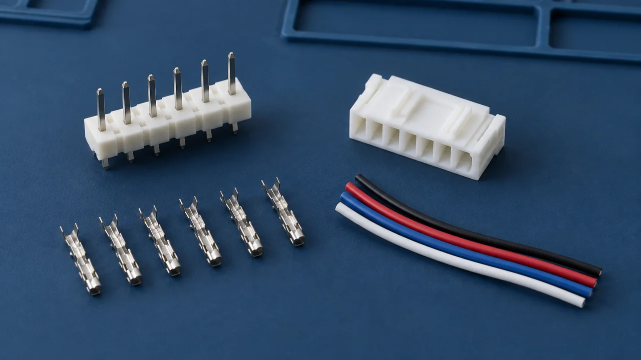
Selecting a wire-to-board connector means selecting more than a plastic housing. The board header, housing, crimp contacts, wire and processing tools all contribute to the completed connection. Start with the electrical load and harness requirements, identify the complete assembly, and then review installation and sample performance. This guide covers common internal crimp-style wire-to-board connections, not direct design decisions for hot-plugging, high-voltage or specialized safety applications.
1. Specify the current and wire together
State whether each current value is continuous, a short peak or associated with a particular load condition. Identify simultaneously loaded circuits, ambient temperature and space constraints. For the wire, specify conductor size, material, construction, insulation outside diameter and temperature-related requirements.
Current ratings have conditions. For example, JST lists the XH family's 3 A rating with AWG 22 wire.[1] That number must not be applied automatically to every smaller wire supported by the series, every loading combination or every operating environment. The example illustrates how to read a rating; it is not a recommendation to use XH for any 3 A load.
Wire selection also requires more than an AWG number. Wires with the same conductor size can have different insulation diameters. Both the conductor crimp and insulation support must match. When the wire is not yet defined, select it together with the terminal rather than ordering contacts first and finding a wire that appears to fit later.
2. Identify the housing, contacts and board header as a set
The housing positions and retains the contacts. The crimp contacts connect to the conductors and provide the mating interface. The board header mates with the harness side and connects to the PCB. Record each complete part number—not just the family name.
The JST XH catalog lists different wire ranges for SXH-001T-P0.6 and SXH-002T-P0.6, while the product page identifies contacts, housings and headers separately.[1][2] A contact from the right family is not automatically suitable for the selected wire. Plating, supply format and required tooling must also match the ordered version.
For cross-brand or cross-series combinations, physical insertion is not proof of a manufacturer-approved mating relationship. A project that requires mixed components should separately document both complete part numbers, supporting information, known differences and validation responsibilities. One component's rating does not become a guarantee for the mixed assembly.
Assembly identification worksheet
| Assembly element | Information to record | Project entry |
|---|---|---|
| PCB header | Complete part number, positions, entry direction, mounting and PCB drawing | ______ |
| Harness housing | Complete part number, polarization or keying, retention mechanism | ______ |
| Crimp contact | Complete part number, wire range, finish and supply format | ______ |
| Wire | Conductor size and construction, insulation diameter, material and conditions of use | ______ |
| Tooling and processing | Specified tool or applicator, process specification and inspection requirements | ______ |
| Other accessories | Secondary locks, seals or supports; state “none” where applicable | ______ |
3. Review retention, cable routing and service access together
Beyond pitch and position count, check top or side entry, the mating path, retention and polarization features. A connection that stays latched is not automatically qualified for the equipment's vibration or cable loads. The actual environment determines what additional evaluation is needed.
Review the harness route and board connector in the same assembly view. Will the installed wire bundle contact the enclosure? Is there room to release a latch with a finger or tool? Where is the harness supported? Must other modules be removed before servicing? A connector outline alone rarely answers all these questions.
Also identify how incorrect mating will be prevented: keying, polarization, physical separation, labeling or work instructions. Color can aid identification, but matching or different colors do not establish the required circuit relationship.
4. A quick pull is not a crimp-quality assessment
Matching the contact and wire range is only the starting point. Wire preparation, crimp height, insulation support and terminal appearance must be controlled against the applicable processing specification. JST's crimping precautions call for specified tooling and identify wire suitability, insulation diameter and crimp height as controlled items.[3]
For a finished harness inquiry, include the wire, contacts, processing requirements and requested inspection records. For loose components, confirm that the intended assembler has the required tools and instructions. A terminal fitting into an existing hand tool is not confirmation of an acceptable process.
There is no universal crimp height, strip length or pull-force acceptance value in this guide. Those values depend on the contact, wire and applicable specification and must be taken from the relevant documentation and project requirements.
5. Complete the selection inputs before comparing quotations
| Requirement group | Questions to answer | Project entry |
|---|---|---|
| Electrical load | Current and voltage per circuit, peak duration and simultaneous loading | ______ |
| Wire and harness | Conductor size, insulation diameter, length, routing and support | ______ |
| Board installation | Positions, pitch, orientation, PCB thickness or layout, and space | ______ |
| Operation | Retention, mistake prevention, mating cycles and service access | ______ |
| Environment and process | Temperature, vibration, contamination, soldering and cleaning | ______ |
| Supply scope | Loose parts or finished harness; sample and production quantities; target date | ______ |
| Validation | Owners for assembly, electrical, process and environmental checks | ______ |
Mark unresolved entries “to be confirmed.” When comparing quotations, ensure that they cover the same assembly. A housing-only price should not be compared directly with a price that includes contacts, wire and harness processing.
6. Test the complete interconnect, not an isolated component
At the sample stage, use the intended PCB, full component set and specified wire. Check circuit mapping, contact seating, retention, harness loading and servicing access. Then assess the crimp, electrical and environmental performance against project requirements, recording the part revisions, processing conditions and sample scope.
The selection result should be an identifiable interconnect assembly, not merely a connector family name. When contacting MISUXIN, provide wire size, operating current, assembly information and quantities, and specify whether the request concerns loose components or a finished harness. The actual supply scope remains subject to confirmation.
Related reading
How to Read a Connector Datasheet: Drawings, Ratings and Test Conditions
How to Prepare a BOM RFQ: Part Numbers, Quantities and Delivery Requirements
References
[1] JST, XH Connector Catalog. PDF p. 1: ratings and their conditions; p. 3: crimp contacts, wire ranges and insulation diameters. The catalog is also available through the official XH product page.
[2] JST, XH Product Page. Product and component lists for housings, contacts and headers; each component must be identified separately.
[3] JST, Precaution for Crimping Process. PDF pp. 1–2 (printed pp. 963–964), sections 1, 2, 3.2 and 3.3: tooling, wire selection, stripping and crimp height. This does not replace the contact-specific process specification.
References accessed September 17, 2026. Product examples illustrate documentation and evaluation methods; they are not part recommendations, interchangeability approvals or supply commitments.