
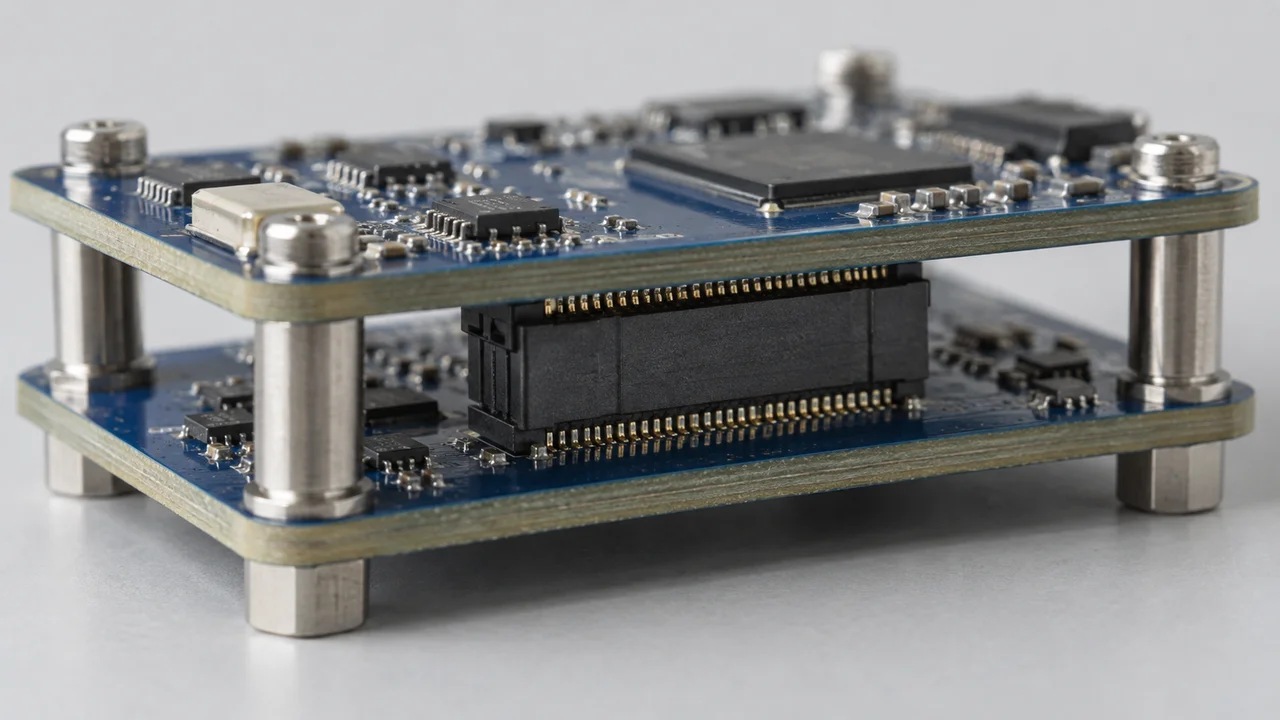
A board-to-board connection consists of two mating parts mounted on separate PCBs. Pitch and position count describe only part of the requirement. Board orientation, the definition of mated spacing and permitted assembly variation also determine which candidates are suitable. This guide addresses initial module-interconnect selection; catalog dimensions and data-rate headlines do not replace system validation.
1. Define the relationship between the two boards
First establish whether the boards are parallel, perpendicular or coplanar, and how they approach and separate during assembly. Samtec's QSH/QTH documentation describes different configurations for these relationships, illustrating why a product-family name alone is insufficient.[1]
Identify board-mounting datums, enclosure restrictions, standoff locations and connector mounting surfaces. A simple sketch can communicate the arrangement, but precise dimensions must come from project drawings, not measurements taken from product images.
Decide how the module will be serviced. Is it assembled once at the factory or replaced in the field? Can the boards separate along a straight path? Could other components interfere first? Use these conditions to eliminate unsuitable structures before selecting a connector, rather than trying to invent a workable assembly sequence afterward.
2. Confirm stack height for the exact mating pair
For parallel boards, interpret stack height according to the reference planes in the manufacturer's mating drawing. Do not add the two unmated component heights. List the complete plug and socket part numbers, including suffixes that determine height or construction.
Samtec's QSH page presents mated stack heights for defined part-number combinations and provides mating-drawing resources.[2] Check the applicable mounting surfaces, mating state and tolerances. Where the enclosure or standoffs define board spacing, compare that dimension using the same reference planes.
Nominal height is not the same as permitted assembly variation. If the fixed board spacing conflicts with the mating requirements, the design needs review. Forcing the parts together or adjusting screw preload to conceal the mismatch is not a valid substitute.
3. Equal pitch does not mean equal footprints or pin assignments
Check positions, rows, contact layout, polarization, locating posts and hold-down features. Confirm position 1 and circuit allocation at both ends, paying particular attention to top views, bottom views and mirrored relationships.
For an existing PCB, compare candidate footprints with the original layout using common coordinates. Include pad dimensions, locating features, solder mask and surrounding clearance. For mating, review lateral offset, parallelism, board bow and mounting tolerances. Do not invent a supposedly typical allowable deviation where the manufacturer has not specified one.
Confirm any guidance, floating or load-bearing capability from the exact product documentation. An ordinary board-to-board connector should not be assumed to provide structural support, and floating capability from one family cannot be transferred to a similar-looking part.
4. Ask different questions for power and high-speed signals
Power circuits require review of current per contact, loading combinations, temperature rise and environment. Signal circuits require the protocol, data rate, pin allocation and channel conditions. For a high-speed path, include PCB traces, vias, reference planes and connector transitions rather than relying on a headline “Gbps” figure.
Samtec's explanation of its Channel Performance Metric, or CPM, uses a predefined complete channel and notes that a customer's application can differ from those assumptions.[3] A connector capability figure therefore does not, by itself, guarantee link performance on the intended PCB.
The scope of each report also matters. Unless otherwise noted, the QSH/QTH specification applies to a vertical configuration with a 5 mm mated height; the product page also separates high-speed reports by mating height.[1][2] Preserve the exact mating pair and test conditions when comparing results.
5. Separate project constraints from candidate comparisons
Board-level requirements worksheet
| Constraint | Information to provide | Status / drawing |
|---|---|---|
| Board relationship | Parallel, perpendicular or coplanar; approach and separation directions | ______ |
| Dimensions and datums | Mating reference planes, nominal spacing, tolerance and mounting surfaces | ______ |
| PCB and support | Board thickness, fixing points, supports, permitted deformation and offset | ______ |
| Layout limits | Fixed or adjustable footprints, keep-outs and locating features | ______ |
| Circuit requirements | Positions, pin mapping, current, protocol, rate and channel conditions | ______ |
| Use and process | Servicing, environment, soldering and inspection conditions | ______ |
Mating-pair comparison worksheet: each candidate column represents a complete pair, not one connector.
| Comparison item | Original design / requirement | Candidate pair A | Candidate pair B |
|---|---|---|---|
| Complete part numbers at both ends | ______ | ______ | ______ |
| Mating drawing and revision | ______ | ______ | ______ |
| Height, datums and tolerances | ______ | ______ | ______ |
| Both PCB footprints and pin assignments | ______ | ______ | ______ |
| Assembly variation and support | ______ | ______ | ______ |
| Electrical and signal evidence | ______ | ______ | ______ |
| Known differences and validation tasks | ______ | ______ | ______ |
The worksheet does not approve a candidate automatically. Mark missing evidence “to be confirmed.” Describe each difference and whether it conflicts with a fixed requirement; an overall score must not hide a critical mismatch.
6. Validate samples in the intended structure
Confirm both sample part numbers and revisions, then check full engagement, servicing access, pin mapping and interference on the intended PCBs and mounting structure. Perform electrical, signal and environmental validation as required by the project. Mating two loose connectors on a bench does not cover the actual board-level constraints.
The resulting record should state which pair was assessed, on which PCB revision, under what conditions and with which checks completed. The objective is to establish a mating relationship that fits the project—not simply to choose a series.
For a requirement discussion, provide the board-relationship drawing, mounting distance and tolerances, signal requirements and quantities. Where existing connectors are involved, include documentation for both sides.
Related reading
How to Read a Connector Datasheet: Drawings, Ratings and Test Conditions
Evaluating Chinese-Brand Connector Alternatives: Mechanical, Electrical and Assembly Checks
References
[1] Samtec, QSH/QTH Product Specification. Revision K, February 20, 2025; p. 2, section 1.1: information applies to the 5 mm mated-height vertical configuration unless otherwise noted.
[2] Samtec, QSH Product and Mating Resources. Prints and Footprints; Mates and Related Components; Full Mated Sets; and test reports for specific mated heights.
[3] Samtec, A New High Speed Connector Rating That Accounts For The Entire System. Published December 6, 2016. Explains the predefined complete channel used for CPM and how a customer application may differ.
References accessed September 17, 2026. Product examples illustrate documentation and evaluation methods; they are not part recommendations, interchangeability approvals or supply commitments.