
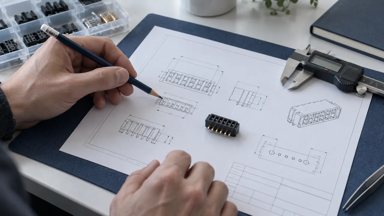
A connector datasheet contains more than pitch, contact count and current rating. Read it in a deliberate order: identify the exact part covered by the document, understand what each drawing shows, and then read every parameter together with its conditions. This turns a collection of specifications into information that can support selection, purchasing and technical review.
1. Match the document to the complete part number
Start by distinguishing a product series from an orderable part number. A series page describes the product family. For an RFQ or design-in, record the manufacturer, complete part number and all relevant suffixes, then obtain the applicable dimensional drawing, specification and mating-component information. A photograph, abbreviated description or internal stock code is not a substitute for the manufacturer's part number.
Hirose's FH12 catalog, for example, uses its part-number structure to identify options such as contact position, mounting configuration and plating. Omitting characters can remove information needed to identify the intended version.[1] A useful document record begins with the complete part number, document title, revision and retrieval date. A download date is not a revision date; record an unmarked revision as “not specified” rather than inventing one.
Check mating components separately. Board-to-board connectors require a mating pair; wire-to-board systems require the appropriate housing, contacts and board header. Samtec's QSH page provides mating-series information, full mated sets, drawings and test reports as separate resources. They need to be read together.[2]
2. Distinguish outline, mating and PCB layout drawings
An outline drawing describes the connector body, locating features and occupied space. A mating drawing describes the relationship between connected parts, including the mating height or insertion position. A recommended land pattern or PCB layout defines pads and holes, while a stencil drawing addresses solder-paste printing. These drawings answer different questions and are not interchangeable.
The FH12 catalog presents recommended FPC/FFC dimensions separately from PCB land and stencil dimensions.[1] Before reading individual measurements, check the drawing title, viewing direction, units and reference datums. A view from the component-mounting side must not be treated as a bottom view without checking. Contact pitch should not automatically be applied to every pad or locating hole.
Read both dimension-specific and general tolerances. Do not estimate unspecified dimensions from an image. For assembly-critical features, record the permitted range, mating feature and reference datum—not just the nominal value.
3. Read the conditions behind every rating
Ratings, test levels, typical values and guaranteed limits mean different things. A rating describes a specified operating limit under stated conditions. A test level may apply only during a short verification procedure. A typical value is not necessarily a guaranteed limit for every unit. Preserve qualifiers such as maximum, minimum, initial and after testing.[1][3]
For example, the FH12 catalog lists rated voltage separately from dielectric-withstanding test voltage, with a duration specified for the latter.[1] The test voltage must not be used as the continuous operating voltage. Similarly, read current capability together with the number of simultaneously energized contacts, temperature and other applicable notes. Multiplying a single-contact rating by the number of positions does not establish an unconditional current capacity for the whole connector.
Also identify the tested configuration. The QSH/QTH specification states that, unless otherwise noted, its information applies to a vertical configuration with a 5 mm mated height.[3] That qualification must remain attached to any extracted data. It cannot be extended automatically to every height or mounting style in the family.
4. Build a datasheet review record
The following template helps turn reading into a reviewable record. Enter actual pages or sections rather than simply writing “manufacturer website.”
| Document section | Information to record | Conditions to retain | Questions to resolve |
|---|---|---|---|
| Ordering guide or individual product page | Manufacturer, full part number and suffixes | Intended construction and packaging | Missing characters or conflicting identifiers |
| Mating-component information | Both mating part numbers or the complete assembly | Required contact count and configuration | Whether the manufacturer specifies the mating relationship |
| Outline and mating drawings | Datums, dimensions, tolerances and orientation | Unmated and mated dimensions distinguished | Missing critical dimensions or tolerances |
| PCB and stencil drawings | Pads, holes and stencil openings | Viewing side, units and revision | Suitability for the intended PCB process |
| Electrical characteristics | Ratings, limits and test levels | Temperature, load, measurement and duration | Data missing for the intended operating conditions |
| Mechanical, environmental and handling information | Mating, retention, environmental and operating limits | Applicable assembly and test conditions | Whether the actual installation falls within that scope |
This is a reading aid, not a certificate of conformity. The design or quality team must still decide whether the evidence covers the project's requirements.
5. Ask questions that can be answered precisely
Replace “Will this connector work?” with a specific question: “How many contacts are energized for this current rating?” “Which reference planes define the board spacing?” or “Does this suffix change the mating component or PCB footprint?”
When a catalog, product page and drawing disagree, do not select whichever value is most convenient. Record the conflict and seek clarification from the manufacturer or an authorized technical representative. Leaving a point “to be confirmed” is more useful than filling it with an unsupported conclusion.
A completed datasheet review should identify the exact part, the documents used, the conditions already established and the questions that remain open. That record provides a stronger starting point for selection than a list of headline specifications.
For the next step, use the FPC/FFC connector selection guide to organize drawings, application conditions and quantities into a project requirement.
Related reading
FPC/FFC Connector Basics: Pitch, Contact Orientation and Locking Mechanisms
FPC/FFC Connector Selection Guide: From Cable Dimensions to Assembly Space
References
[1] Hirose, FH12 Series Catalog. Document D31648_en; printed p. 2: specifications and ordering; p. 3: configurations; p. 10: FPC/FFC, PCB land and stencil dimensions. Confirm the drawing and revision for the intended part.
[2] Samtec, QSH Product and Mating Resources. Prints and Footprints; Mates and Related Components; Full Mated Sets; and test reports for specific mated heights.
[3] Samtec, QSH/QTH Product Specification. Revision K, February 20, 2025; p. 2, section 1.1: information applies to the 5 mm mated-height vertical configuration unless otherwise noted.
References accessed September 17, 2026. Product examples illustrate documentation and evaluation methods; they are not part recommendations, interchangeability approvals or supply commitments.