
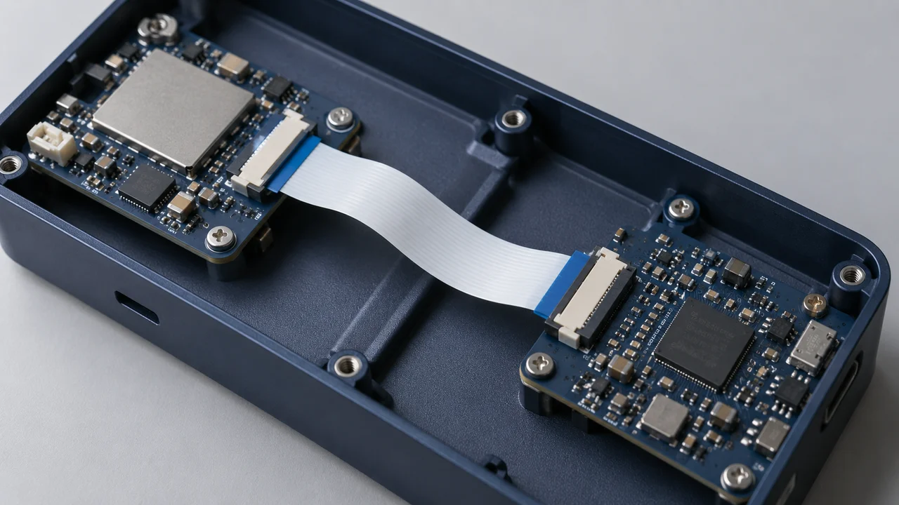
Start FPC/FFC connector selection with the cable and mechanical constraints already established, rather than choosing an attractive-looking part from a catalog. The objective is to align the cable interface, PCB layout, assembly operation and electrical requirements into a shortlist that can be quoted and sampled. Shortlisting does not replace project validation.
1. Identify what is fixed and what can change
A new design and an existing board start from different constraints. A new project may allow the cable and connector to be selected together. An existing PCB, display module or customer-specified cable can fix the mating geometry, footprint or available space.
Identify who supplies the cable, who controls the PCB design and who approves changes. Mark established requirements as “fixed,” state the permitted range for adjustable items, and leave unresolved items “to be confirmed.” An unknown requirement is not permission for a supplier to decide it independently.
Even when an existing part number is available, obtain the cable-end drawing and board-level information. The part number helps locate documentation but does not describe every application condition. Photographs can show location and orientation; they are not precision dimensional references.
2. Match the cable end, then verify the circuit mapping
For the first screening pass, check pitch, number of positions, total mating-end thickness and tolerance, end width, exposed conductor length, stiffener geometry and contact orientation. Compare each item with the connector's recommended mating-end drawing, rather than stopping at “0.5 mm, 20 positions.” Hirose's FH12 catalog separates cable-end requirements from PCB layout requirements, making this distinction explicit.[1]
Next, establish the electrical mapping. Mark position 1 at both ends, show the exposed conductor surfaces and explain the cable's installed orientation, including any folds. Use drawings or an explicit pin-to-pin table. Mechanical insertion alone does not establish that power, ground and signals reach the correct circuits.
When the cable has not been finalized, agree its mating-end specification with the cable supplier. When it is fixed, do not try to adapt it through unapproved thinning, forced insertion or other modifications.
3. Include the assembly motion—not just the connector outline
Check the body dimensions, recommended land pattern, hold-down tabs, locating features and keep-out areas. Also allow room to open the actuator, insert the cable and remove it during servicing. A connector fitting inside the enclosure does not mean an operator can assemble it there.
Near a shield or enclosure wall, the actuator's open-state clearance may differ substantially from its closed-state envelope. Cable approach, bend location and assembly sequence can further restrict the options. These points should be reviewed with mechanical and assembly personnel, not inferred from product photographs alone.
Hirose's individual FH12 product information lists pitch, contact count, contact position and mounting type separately. Treat them as independent selection conditions rather than summarizing everything as a “flip-lock connector.”[2] To retain an existing PCB, compare the candidate footprint with the original layout using common datums; overall size alone is insufficient.
4. Check electrical, environmental and service conditions
Record the operating current and voltage of each circuit, simultaneous loading, ambient temperature and any signal requirements needing specific assessment. Evaluate the cable and connector as parts of the same interconnect path rather than relying on one component's rating.
Manufacturer ratings apply under defined conditions. A connector rating is not an unconditional rating for the complete cable assembly, and a dielectric-withstanding test voltage is not the operating voltage. When the intended conditions are not covered by the documentation, request clarification instead of applying an arbitrary universal safety factor.[1]
Describe how the connection will be used. Will it remain assembled, or be disconnected during maintenance? Will the cable experience vibration, pulling, repeated flexing or a special cleaning process? These details determine what must be checked and tested; a basic catalog parameter does not establish suitability for every environment.
5. Turn the requirements into a shortlist
Use the following worksheet. Distinguish “not yet decided” from “no requirement,” and identify drawing numbers and revisions in the attachment field.
| Requirement | Information to provide | Status / attachment |
|---|---|---|
| Project and stage | New design, existing PCB or redesign; prototype or production | ______ |
| Cable identity | FPC or FFC; manufacturer and part number; end-drawing revision | ______ |
| Mating-end geometry | Pitch, positions, thickness tolerance, width, exposed conductors and stiffener | ______ |
| Circuit mapping | Position 1, exposed conductor sides, pin mapping and installed orientation | ______ |
| PCB and envelope | Fixed or adjustable footprint; length, width, height and keep-outs | ______ |
| Mechanism and access | Entry direction, actuator type, opening and removal clearance | ______ |
| Electrical and environmental | Current, voltage, simultaneous loading, temperature and signals | ______ |
| Process and use | Soldering process, service cycles, cable support and applied loads | ______ |
| Commercial and validation | Sample and production quantities, target date and approval owner | ______ |
Classify candidates as meeting fixed requirements, having identified differences, or requiring more information. Do not rank them by price alone. A candidate without adequate cable-interface or PCB-layout information remains unresolved and should not be treated as approved for purchase.
6. Validate the actual assembly at the sample stage
Check samples with the intended cable, PCB and enclosure. Confirm part numbers and revisions, then inspect alignment, full insertion, actuator operation, cable loading and circuit mapping. Carry out electrical and environmental validation according to project requirements. The project team should define the methods, conditions and acceptance criteria.
A part may pass drawing review but leave too little room to operate its actuator in the real enclosure. Documentation identifies which candidates are worth testing; assembly and system validation establish whether a candidate is suitable for the project. These stages should not be compressed into a single “compatible” label.
When discussing requirements with MISUXIN, include the cable-end drawing, PCB restrictions, existing part number or candidate range, and quantities. Mark unresolved information clearly so that missing inputs can be addressed before candidate selection progresses.
Related reading
FPC/FFC Connector Basics: Pitch, Contact Orientation and Locking Mechanisms
How to Prepare a Request for Chinese-Brand Component Alternatives
References
[1] Hirose, FH12 Series Catalog. Document D31648_en; printed p. 2: specifications and ordering; p. 3: configurations; p. 10: FPC/FFC, PCB land and stencil dimensions. Confirm the drawing and revision for the intended part.
[2] Hirose, FH12-10S-0.5SH(55) Product Information. Product specifications. Used to illustrate a complete part number, position count, pitch and contact location, not as a selection recommendation or availability statement.
References accessed September 17, 2026. Product examples illustrate documentation and evaluation methods; they are not part recommendations, interchangeability approvals or supply commitments.