
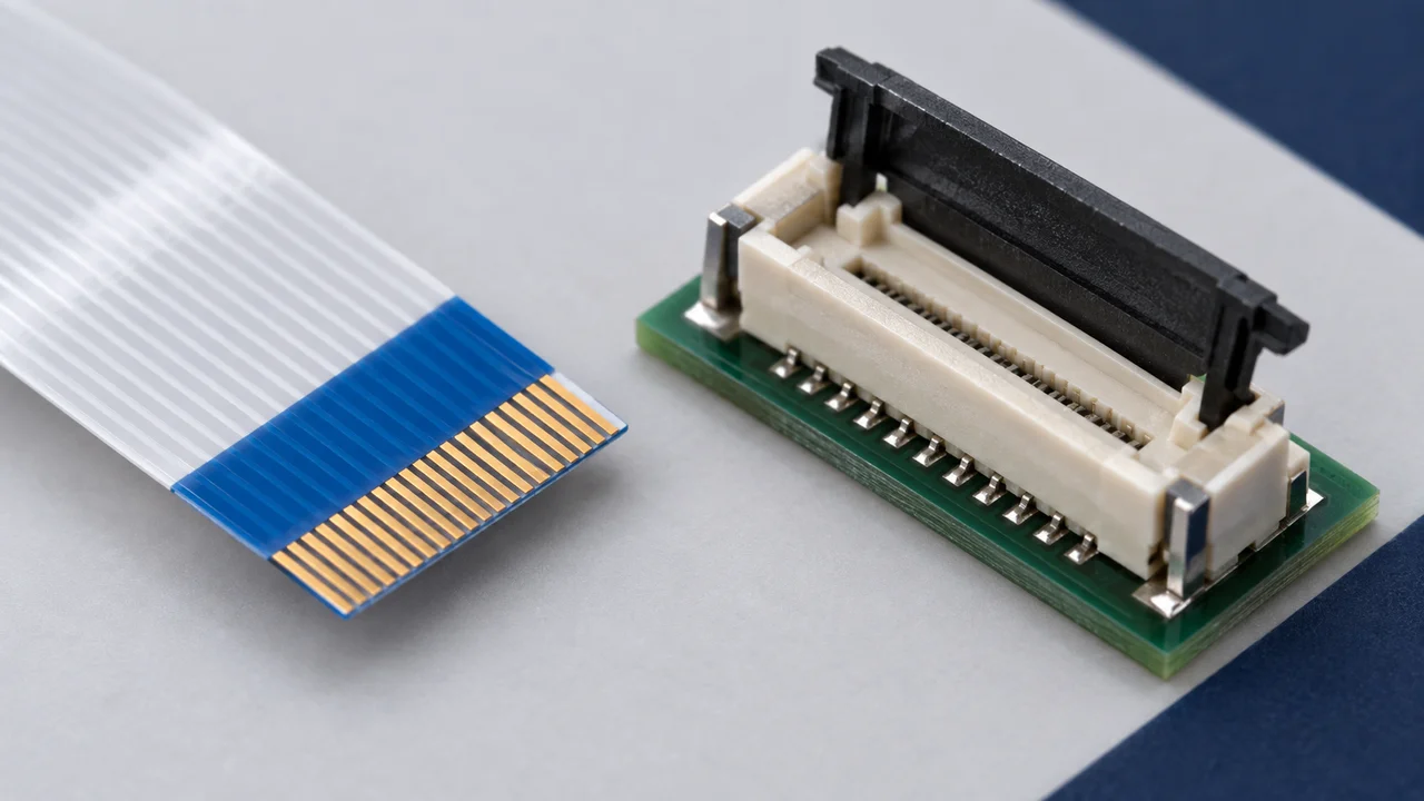
“0.5 mm pitch, 20 positions, flip-lock” describes only part of an FPC/FFC connector. It does not establish whether the connector matches a particular cable. Clear communication also requires the cable type, exposed conductor orientation and mating-end dimensions. Understanding these terms is the first step toward an effective selection request.
1. FPCs, FFCs and connectors are different items
An FPC, or flexible printed circuit, carries conductive traces on a flexible substrate and can incorporate routing or mounted components according to its design. The term describes a circuit construction, not simply something that looks like a flexible cable.[1] An FFC, or flat flexible cable, commonly consists of parallel conductors combined with insulating materials in a flat form. Its length, termination geometry and electrical characteristics depend on the specific cable.[2]
Here, an FPC/FFC connector means a PCB-mounted connector designed to accept a specified flexible mating end. This does not cover every method of connecting flexible circuits. A product title containing both “FPC” and “FFC” does not mean it accepts any cable of either type. Check the mating-end construction explicitly supported by the connector.
2. Pitch and position count describe different dimensions
Pitch is the center-to-center distance between adjacent contact positions. The number of positions or contacts identifies the electrical contact locations; hold-down tabs should not be counted as signal positions. Read the connector contact arrangement, cable conductor layout and PCB terminations from their respective drawings.[3]
For a row of N equally spaced centers, the distance between the first and last center is (N−1) × pitch. This is a geometric relationship, not the overall cable width or connector length. For example, 20 centers at a pitch of 0.5 mm span 9.5 mm from first to last center. Edge margins, the housing and retention features are not included. This calculation does not replace a manufacturer's dimensional drawing.
3. Define the viewing direction before saying “top contact”
For a common horizontal-entry arrangement, imagine a side view with the PCB below the connector and the cable entering from left to right. In a bottom-contact design, the contact points engage the lower side of the mating cable; in a top-contact design, they engage the upper side. Hirose's FH12 catalog distinguishes bottom-contact, top-contact and vertical configurations. The mating drawing for the exact part remains the controlling reference.[3]
Conceptual orientation: side view, PCB below, cable entering horizontally from left to right.
| Item to check | Bottom-contact arrangement | Top-contact arrangement |
|---|---|---|
| Contact location | Below the mating cable | Above the mating cable |
| Conductive mating surface | Lower exposed conductors engage the contacts | Upper exposed conductors engage the contacts |
| Shared viewing convention | PCB below; cable enters horizontally | PCB below; cable enters horizontally |
| Final confirmation | Exact connector mating drawing and cable-end drawing | Exact connector mating drawing and cable-end drawing |
This table explains relative direction only. It is not a manufacturing drawing or an actual product cross-section and does not define contact profiles, dimensions or pin numbering. Do not apply it unmodified to vertical-entry, dual-contact or special constructions.
“Same-side or opposite-side exposed conductors at the two cable ends” is a separate question from “top or bottom contact at one connector.” The first describes the relationship between cable ends; the second describes a connector interface. Supply drawings of both cable ends, marking the conductive surfaces and position 1, rather than relying only on labels such as “Type A” or “Type B.”
4. Mating thickness and actuator style must be checked separately
Mating thickness refers to the stack-up at the region inserted into the connector—not necessarily the thickness of the flexible section farther along the cable. Confirm the conductor, insulation, stiffener and other relevant layers against the cable drawing and the connector's permitted range. The FH12 catalog specifies thickness requirements for that family; those requirements are not universal FPC/FFC dimensions.[3]
ZIF means zero insertion force. It describes insertion with the contact mechanism in the specified open state. It does not permit unrestricted pulling or cable removal with the actuator closed. The FH12 family uses a rotating mechanism, and insertion, locking and removal should follow the applicable handling instructions.[4]
Front-flip, back-flip, slide-lock and one-action mechanisms are different structural descriptions. “Flip-lock” alone does not define contact orientation, mating thickness or operating clearance. Record these as separate selection fields.
5. Use consistent terminology in drawings and RFQs
| Term | Meaning | Information to specify |
|---|---|---|
| Pitch | Spacing between adjacent contact centers | Which contact row and the value in mm |
| Positions / contacts | Electrical contact locations | Count separately from hold-down tabs |
| Top / bottom contact | Side of the cable engaged by the contacts | Viewing direction, PCB position and exposed conductors |
| Mating thickness | Total thickness at the insertion region | Nominal thickness and tolerance |
| Stiffener | Reinforcement at a defined cable region | Location, material and contribution to end thickness |
| Actuator / lock | Mechanism used to open, close or retain the connection | Operating method, direction and clearance |
| ZIF | Zero-insertion-force arrangement | Required mechanism state during insertion |
| Insertion direction | Cable approach relative to the PCB | Horizontal or vertical entry |
6. Recognizing the structure is only the beginning
Matching pitch and contact count narrows the search; matching color or actuator appearance does not prove compatibility. Even when a cable can be inserted, contact position, dimensional tolerances, PCB layout, ratings and actual assembly still need to be checked.[3]
For an initial inquiry, provide the cable-end drawing, intended or existing connector part number, exposed conductor orientation and available board space. Describe the mating relationship, not just the appearance. That makes the request useful for both engineering review and sourcing.
Related reading
How to Read a Connector Datasheet: Drawings, Ratings and Test Conditions
FPC/FFC Connector Selection Guide: From Cable Dimensions to Assembly Space
References
[1] Molex, Flexible Printed Circuits (FPCs). FAQ: “What are flexible printed circuits (FPCs)?” Definition and flexible-substrate construction.
[2] Molex, Premo-Flex Flat Flexible Cables (FFC/FPCs). Product overview and cable configurations. Mating-end and electrical requirements depend on the specific configuration.
[3] Hirose, FH12 Series Catalog. Document D31648_en; printed p. 2: specifications and ordering; p. 3: configurations; p. 10: FPC/FFC, PCB land and stencil dimensions. Confirm the drawing and revision for the intended part.
[4] Hirose, FH12 Series Overview. Features, structural configurations and actuator information.
References accessed September 17, 2026. Product examples illustrate documentation and evaluation methods; they are not part recommendations, interchangeability approvals or supply commitments.